Bridge bearings
Bridge bearings
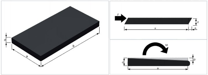
Elastomer bearings
Elastomer bearings are layered products, i. e. they alternate between an elastomer layer and a steel panel as reinforcement for the part.
The entirety is vulcanised to permanently attach the rebar with the elastomer layers.
The main component used in manufacture is polychloroprene rubber, reinforcement is made of enhanced quality steel type S355 J0.
The reinforced elastomer blocks are used in engineering structures to transfer reactions from vertical and horizontal loads to the support parts; they also provide freedom of deformation for stays and the walkway platform, which are a result of temperature changes.
Product description
Support for drive-on components of engineering structures: bridges, viaducts, pedestrian flyovers – is constructed in most cases through the use of flexible components. Elastomer bearings are such components. The load resistance is ensured by internal reinforcement with steel panels. These bearings are made of polychloroprene rubber or natural rubber.
Thanks to different types of bearings, it is possible to satisfy all that is required of them in engineering structures.
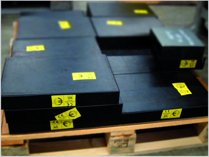
According to Polish Standard PN-EN 1337-3, structural elastomer bearings possess the CE mark, confirming the adherence to particular requirements of the indicated norm by the manufacturer, in this case the company Gumba GmbH. The CE mark issued to the elastomer structural bearings made by Gumba GmbH by MPA Stuttgart, a notified body within the European Union, unequivocally conforms the adherence to requirements of standard PN-EN 1337-3. This document permits the introduction of the bridge bearings onto the European market, including the Polish market.
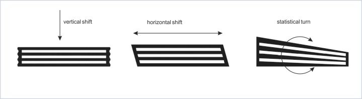
Elastomer properties allow, to a certain degree, movement of the material itself and twisting by deformation. As compared to other bearing types, they have a certain particular advantage – in many cases one can forgo expensive structures with slip components. If the shift caused by the properties of the elastomer bearing is not sufficient for a particular case, the scope of functionality may be expanded.
Note:
As a result of errors during design and bearing selection, locking of the structure may occur, as well as pressure of the main structure on the abutments, and following that – cracking of front walls, head walls and lower plinths. Altering bearing dimensions also causes flaws, and as a result, it needlessly increases costs of construction and maintenance of the structure.
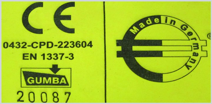
Every elastomer bearing has a vulcanised label describing the bearing, which contains the following information (image below):
- CE certificate number
- norm according to which the bearing was manufactured
- manufacturer logo
- bearing number
 |
 |
Bearing types
Considering the anchoring method, one can differentiate between four basic elastomer bearing types: type B(1), type C(2), type B/C(1/2) and type C-PSP(5).

Type B(1) – reinforced, non-anchored bearing, consisting of at least two steel reinforcement plates. Fulfilment of the condition of minimum load and friction prevents this bearing from slipping. Lack of anchoring eases replacement and servicing of these bearings.

Type B/C(1/2) – reinforced bearing with single-side anchoring. The vulcanised external rubber prevents this bearing from slipping, and forms the lower support surface of the part. The method of anchoring of the bearing may be freely configured: welded anchors, protective circular plates or threaded holes. For railway bridges, irrespective of the loads, type B/C(1/2) should always be used.
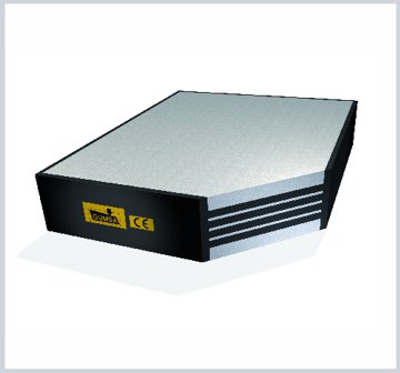
Type C(2) – reinforced bearing, anchored on both sides. The vulcanised external sheet steel (support surfaces) prevent this bearing from slipping. Similarly to the type described earlier, the method of anchoring of the bearing is freely selectable: welded anchors, protective circular plates or threaded holes. Replacement of this bearing type is quite complicated, and requires additional operations.
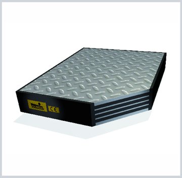
Type C-PSP(5) – reinforced bearing, anchored on both sides. Vulcanised external ribbed metal sheets (support surfaces) prevent this bearing from slipping. The replacement of this bearing type is quite complicated, and requires not only the grout under the bearing, but also the reinforced concrete part above the bearing, to be removed.
Standard Gumba bearing dimension tables
| Minimum pressure ≥ 3N/mm² |
Minimum pressure < 3 N/mm² |
|||||||||||||
| Typ B(1) | Typ C (2) i C (5) |
Typ B/C (1/2) |
||||||||||||
| Load Nz,k |
Bearing dimensions a x b |
Elastomer layer count n |
Shift +/- ex |
Bearing height d |
Elastomer thickness t |
Shift +/- ex |
Bearing thickness Typ 2 d |
Bearing thickness Typ 5 d |
Elastomer thickness t |
Shift +/- ex |
Bearing thickness d |
Elastomer thickness t |
Turn angle Ø |
|
| kN |
mm |
pcs. |
mm |
mm |
mm |
rad/1000 | ||||||||
| 100 150 |
100×100 100×150 |
1 | 7 | 14 | 10 | – | – | – | – | – | – | – | 4 | |
| 2 | 11 | 21 | 15 | 7 | 42 | 32 | 10 | 9 | 31,5 | 12,5 | 8 | |||
| 3 | 14 | 28 | 20 | 11 | 49 | 39 | 15 | 12 | 38,5 | 17,5 | 12 | |||
| 4 | 16 | 35 | 25 | 14 | 56 | 46 | 20 | 15 | 45,5 | 22,5 | 16 | |||
| 5 | 18 | 42 | 30 | 16 | 63 | 53 | 25 | 17 | 52,5 | 27,5 | 20 | |||
| 6 | – | – | – | 18 | 70 | 60 | 30 | – | – | – | 24 | |||
| 300 | 150×200 | 1 | 7 | 14 | 10 | – | – | – | – | – | – | – | 3 | |
| 2 | 11 | 21 | 15 | 7 | 42 | 32 | 10 | 9 | 31,5 | 12,5 | 6 | |||
| 3 | 14 | 28 | 20 | 11 | 49 | 39 | 15 | 12 | 38,5 | 17,5 | 9 | |||
| 4 | 18 | 35 | 25 | 14 | 56 | 46 | 20 | 16 | 45,5 | 22,5 | 12 | |||
| 5 | 21 | 42 | 30 | 18 | 63 | 53 | 25 | 19 | 52,5 | 27,5 | 15 | |||
| 6 | 23 | 49 | 35 | 21 | 70 | 60 | 30 | 22 | 59,5 | 32,5 | 18 | |||
| 7 | 25 | 56 | 40 | 23 | 77 | 67 | 35 | 24 | 66,5 | 37,2 | 21 | |||
| 8 | 27 | 63 | 45 | 25 | 84 | 74 | 40 | 26 | 73,5 | 42,5 | 24 | |||
| 9 | 28 | 70 | 50 | 27 | 91 | 81 | 45 | 28 | 80,5 | 47,5 | 27 | |||
| 10 | – | – | – | 28 | 98 | 88 | 50 | – | – | – | 30 | |||
| 310 630 750 1000 |
ø200 200×250 200×300 200×400 |
1 | 9 | 19 | 13 | – | – | – | – | – | – | – | 3 | 4 |
| 2 | 15 | 30 | 21 | 11 | 49 | 39 | 16 | 13 | 39,5 | 18,5 | 6 | 8 | ||
| 3 | 20 | 41 | 29 | 17 | 60 | 50 | 24 | 19 | 50,5 | 26,5 | 9 | 12 | ||
| 4 | 26 | 52 | 37 | 22 | 71 | 61 | 32 | 24 | 61,5 | 34,5 | 12 | 16 | ||
| 5 | 30 | 63 | 45 | 28 | 82 | 72 | 40 | 29 | 72,5 | 42,5 | 15 | 20 | ||
| 6 | 34 | 74 | 53 | 32 | 93 | 83 | 48 | 33 | 83,5 | 50,5 | 18 | 24 | ||
| 7 | 36 | 85 | 61 | 35 | 104 | 94 | 56 | 36 | 94,5 | 58,5 | 21 | 28 | ||
| 8 | – | – | – | 37 | 115 | 105 | 64 | – | – | – | 24 | 32 | ||
| Minimum pressure ≥ 3N/mm² |
Minimum pressure < 3 N/mm² |
|||||||||||||
| Typ B(1) | Typ C (2) i C (5) |
Typ B/C (1/2) |
||||||||||||
| Load Nz,k |
Bearing dimensions a x b |
Elastomer layer count n |
Shift +/- ex |
Bearing height d |
Elastomer thickness t |
Shift +/- ex |
Bearing thickness Typ 2 d |
Bearing thickness Typ 5 d |
Elastomer thickness t |
Shift +/- ex |
Bearing thickness d |
Elastomer thickness t |
Turn angle Ø |
|
| kN |
mm |
szt. |
mm |
mm |
mm |
rad/1000 |
||||||||
| 600 1300 |
Ø250 250×400 |
1 | 9 | 19 | 13 | – | – | – | – | – | – | – | 3 | 4 |
| 2 | 15 | 30 | 21 | 11 | 49 | 39 | 16 | 13 | 39,5 | 18,5 | 5 | 8 | ||
| 3 | 20 | 41 | 29 | 17 | 60 | 50 | 24 | 19 | 50,5 | 26,5 | 8 | 12 | ||
| 4 | 26 | 52 | 37 | 22 | 71 | 61 | 32 | 24 | 61,5 | 34,5 | 10 | 16 | ||
| 5 | 32 | 63 | 45 | 28 | 82 | 72 | 40 | 30 | 72,5 | 42,5 | 13 | 20 | ||
| 6 | 37 | 74 | 53 | 34 | 93 | 83 | 48 | 35 | 83,5 | 50,5 | 15 | 24 | ||
| 7 | 40 | 85 | 61 | 38 | 104 | 94 | 56 | 39 | 94,5 | 58,5 | 18 | 28 | ||
| 8 | 43 | 96 | 69 | 41 | 115 | 105 | 64 | 42 | 105,5 | 66,5 | 20 | 32 | ||
| 9 | 46 | 107 | 77 | 44 | 126 | 116 | 72 | 45 | 116,5 | 74,5 | 23 | 36 | ||
| 10 | – | – | – | 46 | 137 | 127 | 80 | – | – | – | 25 | 40 | ||
| 900 1800 |
Ø300 300×400 |
1 | 9 | 19 | 13 | – | – | – | – | – | – | – | 2 | 3 |
| 2 | 15 | 30 | 21 | 11 | 49 | 39 | 16 | 13 | 39,5 | 18,5 | 4 | 6 | ||
| 3 | 20 | 41 | 29 | 17 | 60 | 50 | 24 | 19 | 50,5 | 26,5 | 6 | 9 | ||
| 4 | 26 | 52 | 37 | 22 | 71 | 61 | 32 | 24 | 61,5 | 34,5 | 8 | 12 | ||
| 5 | 32 | 63 | 45 | 28 | 82 | 72 | 40 | 30 | 72,5 | 42,5 | 10 | 15 | ||
| 6 | 37 | 74 | 53 | 34 | 93 | 83 | 48 | 35 | 83,5 | 50,5 | 12 | 18 | ||
| 7 | 43 | 85 | 61 | 39 | 104 | 94 | 56 | 41 | 94,5 | 28,2 | 14 | 21 | ||
| 8 | 46 | 96 | 69 | 44 | 115 | 105 | 64 | 45 | 105,5 | 66,5 | 16 | 24 | ||
| 9 | 50 | 107 | 77 | 48 | 126 | 116 | 72 | 49 | 116,5 | 74,5 | 18 | 27 | ||
| 10 | 52 | 118 | 85 | 51 | 137 | 127 | 80 | 52 | 127,5 | 82,5 | 20 | 30 | ||
| 11 | 55 | 129 | 93 | 53 | 148 | 138 | 88 | 54 | 138,5 | 90,5 | 22 | 33 | ||
| 12 | – | – | – | 56 | 159 | 149 | 96 | – | – | – | 24 | 36 | ||
| 1200 | Ø350 | 1 | 11 | 24 | 16 | – | – | – | – | – | – | – | 4 | |
| 2 | 19 | 39 | 27 | 15 | 56 | 46 | 22 | 17 | 47,5 | 24,5 | 8 | |||
| 3 | 27 | 54 | 38 | 23 | 71 | 61 | 33 | 25 | 62,5 | 33,5 | 12 | |||
| 4 | 34 | 69 | 49 | 31 | 86 | 76 | 44 | 33 | 77,5 | 46,5 | 16 | |||
| 5 | 42 | 84 | 60 | 39 | 101 | 91 | 55 | 40 | 92,5 | 57,5 | 20 | |||
| 6 | 50 | 99 | 71 | 46 | 116 | 106 | 66 | 48 | 107,5 | 68,5 | 24 | |||
| 7 | 55 | 114 | 82 | 52 | 131 | 121 | 77 | 53 | 122,5 | 79,5 | 28 | |||
| 8 | 59 | 129 | 93 | 57 | 146 | 136 | 88 | 58 | 137,5 | 90,5 | 32 | |||
| 9 | 63 | 144 | 104 | 61 | 161 | 151 | 99 | 62 | 152,5 | 101,5 | 36 | |||
| 10 | 66 | 159 | 115 | 64 | 176 | 166 | 110 | 65 | 167,5 | 112,5 | 40 | |||
| Minimum pressure ≥ 5 N/mm² |
Minimum pressure < 5 N/mm² |
|||||||||||||
| Typ B(1) | Typ C (2) i C (5) |
Typ B/C (1/2) |
||||||||||||
| Load Nz,k |
Bearing dimensions a x b |
Elastomer layer count n |
Shift +/- ex |
Bearing height d |
Elastomer thickness t |
Shift +/- ex |
Bearing thickness Typ 2 d |
Bearing thickness Typ 5 d |
Elastomer thickness t |
Shift +/- ex |
Bearing thickness d |
Elastomer thickness t |
Turn angle Ø |
|
| kN |
mm |
pcs. |
mm |
mm |
mm |
rad/1000 |
||||||||
| 2400 | 350×450 | 3 | 27 | 54 | 38 | 23 | 81 | 61 | 33 | 25 | 67,5 | 33,5 | 8 | |
| 4 | 34 | 69 | 49 | 31 | 96 | 76 | 44 | 33 | 82,5 | 46,5 | 10 | |||
| 5 | 42 | 84 | 60 | 39 | 111 | 91 | 55 | 40 | 97,5 | 57,5 | 13 | |||
| 6 | 50 | 99 | 71 | 46 | 126 | 106 | 66 | 48 | 112,5 | 68,5 | 15 | |||
| 7 | 55 | 114 | 82 | 52 | 141 | 121 | 77 | 53 | 127,5 | 79,5 | 18 | |||
| 8 | 59 | 129 | 93 | 57 | 156 | 136 | 88 | 58 | 142,5 | 90,5 | 20 | |||
| 9 | 63 | 144 | 104 | 61 | 171 | 151 | 99 | 62 | 157,5 | 101,5 | 23 | |||
| 10 | 66 | 159 | 115 | 64 | 186 | 166 | 110 | 65 | 172,5 | 112,5 | 25 | |||
| 1900 3000 |
Ø400 400×500 |
3 | 27 | 54 | 38 | 23 | 81 | 61 | 33 | 25 | 67,5 | 35,5 | 6 | 9 |
| 4 | 34 | 69 | 49 | 31 | 96 | 76 | 44 | 33 | 82,5 | 46,5 | 8 | 12 | ||
| 5 | 42 | 84 | 60 | 39 | 111 | 91 | 55 | 40 | 97,5 | 57,5 | 10 | 15 | ||
| 6 | 50 | 99 | 71 | 46 | 126 | 106 | 66 | 48 | 112,5 | 68,5 | 12 | 18 | ||
| 7 | 57 | 114 | 82 | 54 | 141 | 121 | 77 | 56 | 127,5 | 79,5 | 14 | 21 | ||
| 8 | 62 | 129 | 93 | 60 | 156 | 136 | 88 | 61 | 142,5 | 90,5 | 16 | 24 | ||
| 9 | 67 | 144 | 104 | 65 | 171 | 151 | 99 | 66 | 157,5 | 101,5 | 18 | 27 | ||
| 10 | 70 | 159 | 115 | 69 | 186 | 166 | 110 | 70 | 175,5 | 112,5 | 20 | 30 | ||
| 11 | 74 | 174 | 126 | 72 | 201 | 181 | 121 | 73 | 187,5 | 123,5 | 22 | 33 | ||
| 12 | – | – | – | 75 | 216 | 196 | 132 | – | – | – | 24 | 36 | ||
| 2400 4050 |
Ø450 450×600 |
3 | 27 | 54 | 38 | 23 | 81 | 61 | 33 | 25 | 67,5 | 33,5 | 6 | 9 |
| 4 | 34 | 69 | 49 | 31 | 96 | 76 | 44 | 33 | 82,5 | 46,5 | 8 | 12 | ||
| 5 | 42 | 84 | 60 | 39 | 111 | 91 | 55 | 40 | 97,5 | 57,5 | 10 | 15 | ||
| 6 | 50 | 99 | 71 | 46 | 126 | 106 | 66 | 48 | 112,5 | 68,5 | 12 | 18 | ||
| 7 | 57 | 114 | 82 | 54 | 141 | 121 | 77 | 56 | 127,5 | 79,5 | 14 | 21 | ||
| 8 | 65 | 129 | 93 | 62 | 156 | 136 | 88 | 63 | 142,5 | 90,5 | 16 | 24 | ||
| 9 | 70 | 144 | 104 | 67 | 171 | 151 | 99 | 68 | 157,5 | 101,5 | 18 | 27 | ||
| 10 | 74 | 159 | 115 | 72 | 186 | 166 | 110 | 73 | 172,5 | 112,5 | 20 | 30 | ||
| 11 | 78 | 174 | 126 | 76 | 201 | 181 | 121 | 77 | 187,5 | 123,5 | 22 | 33 | ||
| 12 | 82 | 189 | 137 | 80 | 216 | 196 | 132 | 81 | 202,5 | 134,5 | 24 | 36 | ||
| 13 | 85 | 204 | 148 | 83 | 231 | 211 | 143 | 84 | 217,5 | 145,5 | 26 | 39 | ||
| Minimum pressure ≥ 5 N/mm² |
Minimum pressure < 5 N/mm² |
|||||||||||||
| Typ B(1) | Typ C (2) i C (5) |
Typ B/C (1/2) |
||||||||||||
| Load Nz,k |
Bearing dimensions a x b |
Elastomer layer count n |
Shift +/- ex |
Bearing height d |
Elastomer thickness t |
Shift +/- ex |
Bearing thickness Typ 2 d |
Bearing thickness Typ 5 d |
Elastomer thickness t |
Shift +/- ex |
Bearing thickness d |
Elastomer thickness t |
Turn angle Ø |
|
| kN |
mm |
pcs. |
mm |
mm |
mm |
rad/1000 |
||||||||
| 2900 3600 4500 |
Ø 500 Ø 550 500×600 |
3 | 27 | 54 | 38 | 23 | 81 | 61 | 33 | 25 | 67,5 | 33,5 | 6 | 6 |
| 4 | 34 | 69 | 49 | 31 | 96 | 76 | 44 | 33 | 82,5 | 46,5 | 8 | 8 | ||
| 5 | 42 | 84 | 60 | 39 | 111 | 91 | 55 | 40 | 97,5 | 57,5 | 10 | 10 | ||
| 6 | 50 | 99 | 71 | 46 | 126 | 106 | 66 | 48 | 112,5 | 68,5 | 12 | 12 | ||
| 7 | 57 | 114 | 82 | 54 | 141 | 121 | 77 | 56 | 127,5 | 79,5 | 14 | 14 | ||
| 8 | 65 | 129 | 93 | 62 | 156 | 136 | 88 | 63 | 142,5 | 90,5 | 16 | 16 | ||
| 9 | 72 | 144 | 104 | 69 | 171 | 151 | 99 | 71 | 157,5 | 101,5 | 18 | 18 | ||
| 10 | 77 | 159 | 115 | 75 | 186 | 166 | 110 | 76 | 172,5 | 112,5 | 20 | 20 | ||
| 11 | 82 | 174 | 126 | 80 | 201 | 181 | 121 | 81 | 187,5 | 123,5 | 22 | 22 | ||
| 12 | 86 | 189 | 137 | 84 | 216 | 196 | 132 | 85 | 202,5 | 134,5 | 24 | 24 | ||
| 13 | 89 | 204 | 148 | 88 | 131 | 211 | 143 | 89 | 217,5 | 145,5 | 26 | 26 | ||
| 14 | 93 | 219 | 159 | 91 | 146 | 226 | 154 | 92 | 232,5 | 156,5 | 28 | 28 | ||
| 15 | – | – | – | 94 | 161 | 141 | 165 | – | – | – | 30 | 30 | ||
| 4100 5000 6300 |
Ø 600 Ø 650 600×700 |
3 | 35 | 70 | 50 | 32 | 95 | 75 | 45 | 33 | 82,5 | 47,5 | 6 | 6 |
| 4 | 46 | 90 | 65 | 42 | 115 | 95 | 60 | 44 | 102,5 | 62,5 | 8 | 8 | ||
| 5 | 56 | 110 | 80 | 53 | 135 | 115 | 75 | 54 | 122,5 | 77,5 | 10 | 10 | ||
| 6 | 67 | 130 | 95 | 63 | 155 | 135 | 90 | 65 | 142,5 | 92,5 | 12 | 12 | ||
| 7 | 77 | 150 | 110 | 74 | 175 | 155 | 105 | 75 | 162,5 | 107,5 | 14 | 14 | ||
| 8 | 86 | 170 | 125 | 84 | 195 | 175 | 120 | 85 | 182,5 | 122,5 | 16 | 16 | ||
| 9 | 93 | 190 | 140 | 91 | 215 | 195 | 135 | 92 | 202,5 | 137,5 | 18 | 18 | ||
| 10 | 99 | 210 | 155 | 98 | 235 | 215 | 150 | 98 | 222,5 | 152,5 | 20 | 20 | ||
| 11 | 105 | 230 | 170 | 103 | 255 | 235 | 165 | 104 | 242,5 | 167,5 | 22 | 22 | ||
| 12 | 109 | 250 | 185 | 108 | 275 | 255 | 180 | 109 | 262,5 | 182,5 | 24 | 24 | ||
| 13 | 113 | 270 | 200 | 112 | 295 | 275 | 195 | 113 | 282,5 | 197,5 | 26 | 26 | ||
| Minimum pressure ≥ 5 N/mm² |
Minimum pressure < 5 N/mm² |
|||||||||||||
| Typ B(1) | Typ C (2) i C (5) |
Typ B/C (1/2) |
||||||||||||
| Load Nz,k |
Bearing dimensions a x b |
Elastomer layer count n |
Shift +/- ex |
Bearing height d |
Elastomer thickness t |
Shift +/- ex |
Bearing thickness Typ 2 d |
Bearing thickness Typ 5 d |
Elastomer thickness t |
Shift +/- ex |
Bearing thickness d |
Elastomer thickness t |
Turn angle Ø |
|
| kN |
mm |
pcs. |
mm |
mm |
mm |
rad/1000 |
||||||||
| 5800 6600 8400 |
Ø 700 Ø 750 700×800 |
3 | 35 | 70 | 50 | 32 | 95 | 75 | 45 | 33 | 82,5 | 47,5 | 6 | 6 |
| 4 | 46 | 90 | 65 | 42 | 115 | 95 | 60 | 44 | 102,5 | 62,5 | 8 | 8 | ||
| 5 | 56 | 110 | 80 | 53 | 135 | 115 | 75 | 54 | 122,5 | 77,5 | 10 | 10 | ||
| 6 | 67 | 130 | 95 | 63 | 155 | 135 | 90 | 65 | 142,5 | 92,5 | 12 | 12 | ||
| 7 | 77 | 150 | 110 | 74 | 175 | 155 | 105 | 75 | 162,5 | 107,5 | 14 | 14 | ||
| 8 | 88 | 170 | 125 | 84 | 195 | 175 | 120 | 86 | 182,5 | 122,5 | 16 | 16 | ||
| 9 | 98 | 190 | 140 | 95 | 215 | 195 | 135 | 96 | 202,5 | 137,5 | 18 | 18 | ||
| 10 | 105 | 210 | 155 | 103 | 135 | 215 | 150 | 104 | 222,5 | 152,5 | 20 | 20 | ||
| 11 | 112 | 230 | 170 | 110 | 255 | 235 | 165 | 111 | 242,5 | 167,5 | 22 | 22 | ||
| 12 | 118 | 250 | 185 | 116 | 275 | 255 | 180 | 117 | 262,5 | 182,5 | 24 | 24 | ||
| 13 | 123 | 270 | 200 | 121 | 295 | 275 | 195 | 122 | 282,5 | 197,5 | 26 | 26 | ||
| 14 | 127 | 290 | 215 | 126 | 315 | 295 | 210 | 127 | 302,5 | 212,5 | 28 | 28 | ||
| 15 | 131 | 310 | 230 | 130 | 335 | 315 | 225 | 131 | 322,5 | 227,5 | 30 | 30 | ||
| 7500 8500 9600 |
Ø 800 Ø 850 800×800 |
3 | 41 | 79 | 59 | 38 | 104 | 84 | 54 | 40 | 91,5 | 56,5 | 6 | 6 |
| 4 | 54 | 102 | 77 | 50 | 127 | 107 | 72 | 52 | 114,5 | 74,5 | 8 | 8 | ||
| 5 | 67 | 125 | 95 | 63 | 150 | 130 | 90 | 65 | 137,5 | 92,5 | 10 | 10 | ||
| 6 | 79 | 148 | 113 | 76 | 173 | 153 | 108 | 77 | 160,5 | 110,5 | 12 | 12 | ||
| 7 | 92 | 171 | 131 | 88 | 196 | 176 | 126 | 90 | 183,5 | 128,5 | 14 | 14 | ||
| 8 | 104 | 194 | 149 | 101 | 219 | 199 | 144 | 103 | 206,5 | 146,5 | 16 | 16 | ||
| 9 | 115 | 217 | 167 | 113 | 242 | 222 | 162 | 114 | 229,5 | 164,5 | 18 | 18 | ||
| 10 | 124 | 240 | 185 | 122 | 265 | 245 | 180 | 123 | 252,5 | 182,5 | 20 | 20 | ||
| 11 | 131 | 263 | 203 | 129 | 288 | 268 | 198 | 130 | 275,5 | 200,5 | 22 | 22 | ||
| 12 | 138 | 286 | 221 | 136 | 311 | 291 | 216 | 137 | 298,5 | 218,5 | 24 | 24 | ||
| 13 | 144 | 309 | 239 | 142 | 334 | 314 | 234 | 143 | 321,5 | 236,5 | 26 | 26 | ||
| 14 | 149 | 332 | 257 | 147 | 357 | 337 | 252 | 148 | 344,5 | 254,5 | 28 | 28 | ||
| Minimum pressure ≥ 5 N/mm² |
Minimum pressure < 5 N/mm² |
|||||||||||||
| Typ B(1) | Typ C (2) i C (5) |
Typ B/C (1/2) |
||||||||||||
| Load Nz,k |
Bearing dimensions a x b |
Elastomer layer count n |
Shift +/- ex |
Bearing height d |
Elastomer thickness t |
Shift +/- ex |
Bearing thickness Typ 2 d |
Bearing thickness Typ 5 d |
Elastomer thickness t |
Shift +/- ex |
Bearing thickness d |
Elastomer thickness t |
Turn angle Ø |
|
| kN |
mm |
pcs. |
mm |
mm |
mm |
rad/1000 |
||||||||
| 9500 12000 |
Ø 800 900×900 |
3 | 41 | 79 | 59 | 38 | 104 | 84 | 54 | 40 | 91,5 | 56,5 | 5 | 5 |
| 4 | 54 | 102 | 77 | 50 | 127 | 107 | 72 | 52 | 114,5 | 74,5 | 6 | 6 | ||
| 5 | 67 | 125 | 95 | 63 | 150 | 130 | 90 | 65 | 137,5 | 92,5 | 8 | 8 | ||
| 6 | 79 | 148 | 113 | 76 | 173 | 153 | 108 | 77 | 160,5 | 110,5 | 9 | 9 | ||
| 7 | 92 | 171 | 131 | 88 | 196 | 176 | 126 | 90 | 183,5 | 128,5 | 11 | 11 | ||
| 8 | 104 | 194 | 149 | 101 | 219 | 199 | 144 | 103 | 206,5 | 146,5 | 12 | 12 | ||
| 9 | 117 | 217 | 167 | 113 | 242 | 222 | 16 | 115 | 229,5 | 164,5 | 14 | 14 | ||
| 10 | 128 | 240 | 185 | 126 | 265 | 245 | 180 | 127 | 252,5 | 182,5 | 15 | 15 | ||
| 11 | 137 | 263 | 203 | 135 | 288 | 268 | 198 | 136 | 275,5 | 200,5 | 17 | 17 | ||
| 12 | 145 | 286 | 221 | 143 | 311 | 291 | 216 | 144 | 298,5 | 218,5 | 18 | 18 | ||
| 13 | 152 | 309 | 239 | 150 | 334 | 314 | 234 | 151 | 321,5 | 236,5 | 20 | 20 | ||
| 14 | 158 | 332 | 257 | 156 | 357 | 337 | 252 | 157 | 344,5 | 254,5 | 21 | 21 | ||
| 15 | 163 | 355 | 275 | 162 | 380 | 360 | 252 | 163 | 367,5 | 272,5 | 23 | 23 | ||
| 16 | 168 | 378 | 293 | 167 | 403 | 383 | 270 | 391 | 390,5 | 290,5 | 24 | 24 | ||
The tables for reinforced elastomer bearings apply to standard-construction Gumba bearings. They apply to initial dimensions, which only allow a general and fast estimation of the bearing size. The values provided in them are characteristic values for the Serviceability Limit State (SLS). In order to conduct more precise dimensioning of the structural bearings, please contact our representatives in the retail branches, employees of the technical department or alternatively use the software available at the manufacturer’s website at www.gumba.de. The software allows optimum bearing selection. It includes only known bearing dimensions with layered structures according to Gumba standards and regular bearing dimensions according to norm EN 1337-3.
Calculation basis according to EN 1337-3.
Designing and manufacture of elastomer bearings is based on Polish Standard PN-EN 1337-3, which is harmonised with the Construction Directive 89/106/EEC. This norm covers i. e. reinforced elastomer bearings with a surface area of up to 1200 x 1200 mm2, used between temperature values between -25 °C and +50 °C.
Below, the recommended course of calculations, the expansion of which is found in the norm indicated earlier on, is presented.
Remarks and further hints concerning the presented calculation phases are found in standard PN-EN 1337.
For the calculation of values related to elastomer bearings, characteristic load values need to be applies. The proof takes place at the Ultimate Limit State (ULS) for joint deformation stemming from load and shift.
The table above contains information necessary to dimension bearings according to standard PN-EN 1337-3. The table also contains necessary shore conditions. It may serve the determination and description of structural bearing parameters designed for a particular structure.
Note:
According to Polish Standard PN-EN 1337-3, the bridge structure designer presents all necessary data allowing the selection of structural bearings for such a structure. It is not possible for the bearing manufacturer to calculate this data.
Elastomer bearing calculations
The bearings must correspond to the following requirements:
1. Maximum calculational deformation
At any given point of the bearing, the sum of deformations (Ɛt,d) caused by effects of calculational load (Ed) is given by the formula:
Ɛc,d – calculational deformation caused by compressive calculational loads
Ɛq,d – calculational shear deformation caused by calculational horizontal shifts
Ɛɑ,d– calculational deformation caused by the calculational twist angle
KL – load type coefficient
- Calculational deformation caused by compressive calculational loads
Nz,d – vertical force calculational value
G – nominal value of the ordinary non-dilatational strain modulus for an elastomer bearing
Ar – reduced effective area of the elastomer bearing
A’- effective area of a reinforced bearing (surface area of reinforcement sheet steel)
A’ = a’·b’ (for cuboid bearings without openings)
a’ – effective width of reinforced bearing (reinforcement sheet width)
b’ – effective length of reinforced bearing (reinforcement sheet length)
vx,d – maximum horizontal relative shift of a bearing part towards dimension a of the bearing caused by all effects of calculational load
vy,d – maximum horizontal relative shift of a bearing part towards dimension b of the bearing caused by all effects of calculational load
S – shape coefficient
A’- effective area of a reinforced bearing (surface area of reinforcement sheet steel)
A’ = a’·b’ (for cuboid bearings without openings)
a’ – effective width of reinforced bearing (reinforcement sheet width)
b’ – effective length of reinforced bearing (reinforcement sheet length)
lp – circumference of bearing without load
lp=2·(a’+b’)
te – effective thickness of individual elastomer layer at compression
- Calculational shear deformation caused by calculational horizontal shifts.
vxy,d – maximum resultant horizontal relative shift of bearing part obtained from vector sum of vx,d and vy,d
Tq – total elastomer thickness at non-dilatational strain with upper and lower cover
- Calculational deformation caused by calculational twist angle
a’ – effective width of reinforced bearing (reinforcement sheet width)
ɑa,d – turn angle about bearing width a
b’ – effective length of reinforced bearing (reinforcement sheet length)
ɑb,d – turn angle (if applicable) about bearing width b
ti – individual elastomer layer thickness
2. Maximum extension pressure in reinforcement sheets
- Reinforcement plate thickness
Kp – correction coefficient
Kp = 1,3
Nz,d – calculational value of vertical force
t1, t2 – elastomer thickness on both sides of metal sheet
Kh – extension pressure coefficient caused in the reinforcement steel sheet
Kh =1 (without openings)
Kh = 2 (with openings)
Ɣm – partial safety coefficient, Ɣm= 1,0
Ar – reduced effective elastomer bearing area
fy – steel yield strength
3. Limit conditions
- Twist limit condition
For reinforced bearings, the limit turn should not be reached when total vertical compression ∑Vz,d meets the following conditions:
For parallel wall bearings:
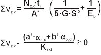
For circular bearings:
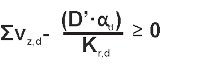
∑vz,d – total vertical compression causing ɑa and ɑb
Nz,d – vertical force calculational value
ti – individual elastomer layer thickness
A’ – effective reinforced bearing area (surface area of reinforcement sheet steel)
G – nominal value of the ordinary non-dilatational strain modulus for an elastomer bearing
S1 – thickest layers shape coefficient
Eb – volumetric strain modulus Eb = 2000 MPa
a’ – effective width of reinforced bearing (reinforcement sheet width)
ɑa,d – turn angle about bearing width a
b’ – effective length of reinforced bearing (reinforcement sheet length)
ɑb,d – turn angle (if applicable) about bearing width b
Kr,d – twist coefficient
Kr,d = 3
D’ – effective bearing diameter
ɑd – twist angle about diameter D of circular bearing
-
Dent stability
In reinforced elastomer bearings, the load should conform to the following formula:
Nz,d – vertical force calculational value
Ar – reduced effective area of the elastomer bearing
a’ – effective width of reinforced bearing (reinforcement sheet width)
G – nominal value of the ordinary non-dilatational strain modulus for an elastomer bearing
S1 – thickest layers shape coefficient
Te – sum total of all elastomer layers
- No-slip condition
Non-anchored bearings must conform to the following formula:
and under fixed loads
Nxy,d – resultant force of all horizontal forces
Nz,dmin – minimum vertical calculational force related to Nxy,d
Ar – reduced effective area of the elastomer bearing
µe – friction coefficient according to the following formula:
Kf = 0,6 for concrete
Kf = 0,2 for all other surfaces including resin mortars and grout
σm – average load tension resulting from Nz,dmin
4. Forces, moments and deformations acting on structures
- mutual contact surface pressure
All that is required is a test whether the average pressure on the surface does not exceed the base layer material strength.
- result force of resistance against horizontal shift
A – total flat bearing area
G – nominal value of the ordinary non-dilatational strain modulus for an elastomer bearing
vxy,d – maximum resultant horizontal relative shift of bearing part obtained from vector sum of vx,d and vy,d
Te – sum total of all elastomer layers
- Rotation resistance
Parallel wall bearings
G – nominal value of the ordinary non-dilatational strain modulus for an elastomer bearing
ɑ – bearing angle of rotation
a’ – effective reinforced bearing width (reinforcement sheet width)
b’ – effective reinforced bearing length (reinforcement sheet length)
n – elastomer layer count
ti – individual elastomer layer thickness
Ks – resistance moment coefficient
Circular bearings
G – nominal value of the ordinary non-dilatational strain modulus for an elastomer bearing
ɑ – bearing angle of rotation
D’ – effective bearing diameter
n – elastomer layer count
ti – individual elastomer layer thickness
The Ks resistance moment coefficient is determined using the following table.
| b/a |
0,5 |
0,75 |
1 |
1,2 |
1,25 |
1,3 |
1,4 |
1,5 |
| Ks | 137 | 100 | 86,2 | 80,4 | 79,3 | 78,4 | 76,7 | 75,3 |
| b/a |
1,6 |
1,7 |
1,8 |
1,9 |
2 |
2,5 |
10 |
X |
| Ks | 74,1 | 73,1 | 72,2 | 71,5 | 70,8 | 68,3 | 61,9 | 60 |
ASSEMBLY RECOMMENDATIONS
General information
Apart from co-operation with design agencies and contractors concerning selection and design of structural bearings, Betomax offers supervision, and, since 2010, also installation of structural bearings. We currently utilise two specialised teams of structural bearing installation specialists. Installation covers arrangement of the bearing on the support structure, levelling and adjusting the bearing with respect to axes, execution of formwork, grouting using low-contraction mortar and protecting the bearing after installation. Our teams are equipped with specialised tools required for correct bearing installation. they utilise the following measurement devices: high-precision levels, electronic levelling instruments, infra-red thermometers and power tools required at installation. The installation concludes with the issue of a bearing installation protocol transferred to the site contractor.
We co-operate with the largest construction companies operating in Poland, i. e. Skanska, Strabag, Polimex Mostostal, Budimex. We have participated in the construction of the first sections of Polish highway A1 and several sections of highway A2. For the installation of structural bearings, we adhere to the current standard PN-EN 1337-11, complying with the strictest EU requirements, as proven by the respect of our satisfied customers.

The installation of a bearing is preceded by creation of image documentation and its transfer to the construction site. After it is approved, preparatory works may commence. The first stage is the execution of lower plinths. The plinths are executed individually for every bearing, considering the hints included in assembly drawings transferred by Betomax. The plinth needs to be reinforced and covered by formwork up to an appropriate height. In case of anchored bearings equipped with studs, openings need to be left clear in the plinth. After appropriate concrete strength is reached, the installation of the bearing may commence. The part on which the grout shall be executed must be prepared accordingly. The bearings are arranged according to the axes indicated by the geodesic services. Then, the bearings are levelled, and their arrangement is checked and approved by a geodesic specialist. A further step is preparing the formwork, after which the grout may be executed. The grout is introduced in a manner ensuring removal of air from under the bearing, so as to avoid emergence of so-called air bubbles under the bearing. Depending on the grout type, after appropriate resistance strength is reached, the load bearing structure of the element may be executed. For transport and assembly, the bearings are protected by assembly securing screws, which must be removed when the structure starts transferring loads and working by itself.

Assembly work
| 1. Preparation of plinth surface by graining | 2. Cleaning of lower plinth surface |
 |
 |
| 3. Assignment of bearings | 4. Layout and levelling of elastomer bearing |
 |
 |
| 5. Grout execution | 6. Securing the bearing |
 |
 |
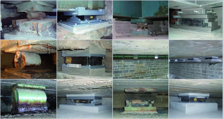
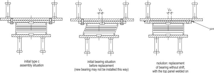
Structural bearing replacement
Extensive investments related to the construction of new road sections and engineering structures are currently carried out in Poland, along with repairs and upgrades of existing structures and roads. In case of existing structures, old, used-up bearings needs to be replaced with new products. Viaducts and bridges often rest on corroded roller bearings which do not work properly, with the entire structure at risk of failure. Betomax offers assistance in the selection of appropriate solutions and in the installation of new bearings. The first stage is designing appropriate bearings, which shall ensure the transfer of vertical loads, horizontal forces and thermal deformations of the existing structure. The above solutions must be accepted by the design office executing the site upgrade design. The replacement of the delivered bearings itself entails lifting the existing structure by hydraulic motors to an appropriate height, thus ensuring the space necessary for removal of the current bearings, in most cases by chiselling them away, and the installation of new bearings.
Professional evaluation of the condition of elastomer bearings requires to a great extent knowledge and experience, and must be conducted by qualified personnel. If divergences are found, consultations with the bearing manufacturer are recommended.
During the inspection of a bridge, structural bearings are also controlled. During an inspection, among others, the following factors are analysed:
- elastomer bearing position
- elastomer bearing contact area size with surrounding surfaces
- quality of elastomer bearing surface (springing effects, cracks)
- allowable horizontal shift
- allowable rotation
- slip surface quality
- corrosion protection quality
Below may be found a few examples of upgrade works completed. Photographs provided by Other Montagen.
| before | after | before | after |